|
GR8677 #94
|
|
|
Problem
|
|
 |
Electromagnetism }LR Circuit }LR Circuit
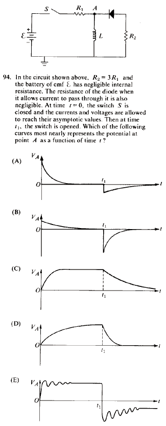
Once the switch S is closed, although the initial current through the inductor is 0, the change in current through it is maximal. Recalling that  , one realizes that the voltage across , one realizes that the voltage across  must be non-zero at the start. Thus, plots (C), (D), and (E) are eliminated. must be non-zero at the start. Thus, plots (C), (D), and (E) are eliminated.
Now, one must decide between choices (A) and (B). Once the circuit reaches equilibrium, i.e., the elements reach their asymptotic values. Specifically, the voltage at A goes to 0, since the inductor has no potential difference across it (to wit  ). Once the switch is opened, the current suddenly changes, and ). Once the switch is opened, the current suddenly changes, and  , thus the inductor has a voltage across it, and the voltage at A becomes nonzero. Because of the diode, this would necessarily have to be a negative voltage. Since there is only , thus the inductor has a voltage across it, and the voltage at A becomes nonzero. Because of the diode, this would necessarily have to be a negative voltage. Since there is only  to dissipate the voltage, the magnitude of the voltage once the switch is opened should be bigger than that initially, when the switch is closed at to dissipate the voltage, the magnitude of the voltage once the switch is opened should be bigger than that initially, when the switch is closed at  . Choose (B). . Choose (B).
|
|
|
Alternate Solutions |
casseverhart13
2019-08-13 09:33:49 | great problem here. . . tree removal |  |
|
|
Comments |
casseverhart13
2019-08-13 09:33:49 | great problem here. . . tree removal |  | psychonautQQ
2013-12-22 20:23:25 | why does having a diode mean that the voltage at point a would have to be negative? first of all it's a zener diode,second of all even if it wasn't i'd still be confused |  | neo55378008
2012-09-06 13:02:52 | We can narrow it down to A or B as the other's pointed out, because we know eventually the energy stored in the inductor will oppose the battery.
As for when the switch is opened, just think of an inductive spike. If you've ever had a device with a transformer near powered speakers, you may have heard a pop in the speakers when the device was turned off. The magnetic field around the conductor collapses, and a voltage spike is made.
B shows this large spike |  | FatheadVT
2010-11-09 14:17:57 | What's the effect of the Ground in this problem?
Almno10
2010-11-12 20:27:39 |
The ground there keeps the potential on that side of the inductor at zero. Thus, when the current starts and stops, the potential at A has a large non-zero magnitude.
|
Almno10
2010-11-12 20:29:36 |
It also forces the potential at A to go to zero as the circuit reaches a steady state, since the inductor will harbor potential difference when the current is steady. The ground is everything here.
|
Almno10
2010-11-12 20:30:40 |
will harbor NO potential difference, that is
|
|  | madfish
2007-11-02 19:12:21 | always remember:
Low Frequencies:
inductors are shorts/Capacitors are open circuits
High Frequencies:
Capacitors are shorts/inductors are open
this will help you out greatly to save time
wangjj0120
2008-08-30 13:03:15 |
What does the comment mean?
Who can explain this~
|
Poop Loops
2008-11-05 23:40:06 |
What that means is that Capacitors cannot pass through DC current. It just builds up. Capacitors only pass current if there is an AC signal.
Conversly, Inductors are great for DC currents, since they are just a loop of wire, so it acts like any other wire. But, when you apply some sort of AC signal, the magnetic field around the loops of wire tries to change, inducing another emf from the Inductor to stop it. So Inductors aren't good at passing through AC current.
That's why when you first flip the switch in this problem, dI/dt is huge so the emf induced in the Inductor is big. It's even bigger when you close the switch because now current flow the *other* way, so dI/dt is twice as big as when you first turned on the switch.
|
|  | Jeremy
2007-10-20 12:53:21 | After eliminating everything but (A) and (B), it made the most sense to me to consider the time constants ( ) for the two RL circuits. For the first decay, ) for the two RL circuits. For the first decay,  , and for the second, , and for the second,  . It is given that . It is given that  , so that , so that  , i.e. , i.e.  . This is answer choice (B). . This is answer choice (B).
alemsalem
2010-09-21 23:25:02 |
Yeah i think this is the way to go, because of the diode current first runs through R1 only, then when the switch is open it runs through R2 only which should take less time to decay.
|
|  | wzm
2006-11-03 11:43:29 | With switch closed, calling emf V, steady state current is

Open the switch and approximate that the inductor momentarily causes the current through it to remain the same. To do this requires the voltage at the top of the inductor to be

*3R{1} = 3V)
This is approximately what is shown in B. |  |
|
|
|
|
The Sidebar Chatbox...
Scroll to see it, or resize your browser to ignore it... |
|
|
|
